Rigid Body Transformations#
A state object holds the variables of a body: its position, its velocity, and, for a rigid body, its attitude. Before these variables can change in time, they need a geometric meaning: in which frame a vector is expressed, and how the orientation of one frame relative to another is described.
This page covers that geometry, with no time involved: the frames of reference, the rotation matrices that move vectors between them, and the three representations of an attitude (Euler angles, rotation matrix, quaternion). The next page, Kinematics, lets these quantities change in time.
In c4dynamics, the geometry is implemented by the rotmat module,
and by the BR and
RB properties of the rigid body
state objects.
Reference Frames#
A frame of reference (or a coordinate system) is an origin and three mutually perpendicular unit axes, \(x, y, z\). A physical vector, such as a velocity or a force, exists independently of any frame. Its three components, however, depend on the frame in which it is resolved. A vector resolved in a given frame is said to be expressed in that frame.
For example, an aircraft that flies north at 150 m/s and pitches up by \(30°\) has a single velocity vector. In an earth frame (north, east, down) its components are \([150, 0, 0]\), while in the aircraft body frame they are \([129.9, 0, 75]\) (see the examples below).
The rate of change of a vector, as viewed by an observer fixed to and moving with a given frame, is said to be relative to (or with respect to) that frame. The laws of motion hold relative to an inertial frame, but the vectors in them can be expressed in any frame.
The frames of c4dynamics
Symbol |
Frame |
Description |
|---|---|---|
\(R\) |
Reference |
The frame in which the state objects express the position and the velocity (\(x, y, z, v_x, v_y, v_z\)), and against which the attitude of a body is defined. |
\(I\) |
Inertial |
A frame that does not accelerate or rotate. The laws of motion hold relative to it. |
\(B\) |
Body |
A frame fixed to the body and rotating with it. The origin is at the center of mass and \(x_b\) is along the centerline (the nose). The body angular rates \((p, q, r)\) and the body components of the velocity \((u, v, w)\) are expressed in this frame. |
\(S\) |
Sensor |
A frame fixed to a sensor, such as a |
Reference, inertial, and earth frames
The reference frame is a modeling choice, and is not necessarily inertial. The equations of motion of c4dynamics, however, are written relative to the reference frame (see Dynamics), and therefore assume that it is inertial. In the use cases, the reference frame is an earth frame: a frame fixed to a flat earth, such as NED or ENU below. The earth rotation and curvature are negligible over the time and the range of these use cases, so the earth frame is treated as inertial, and \(R\) and \(I\) denote the same frame. \(I\) is used where the inertial property matters, e.g. in the navigation sensors and the quadcopter model, and \(R\) elsewhere.
NED and ENU
Two pairs of an earth frame and a body frame are common for vehicles that move
above a flat earth.
Both are supported by the quadcopter model and the navigation sensors through the
frame argument (see Quadcopter):
|
Earth frame |
Body frame |
|---|---|---|
|
\(x\) north, \(y\) east, \(z\) down |
\(x\) forward, \(y\) right, \(z\) down (FRD) |
|
\(x\) east, \(y\) north, \(z\) up |
\(x\) forward, \(y\) left, \(z\) up (FLU) |
Right-handed frames
All the frames in c4dynamics are right-handed:
where \(i, j, k\) are the unit vectors along the \(x, y, z\) axes. Positive rotations are clockwise when viewed from the origin, looking out along the positive direction of the axis (Fig-1).
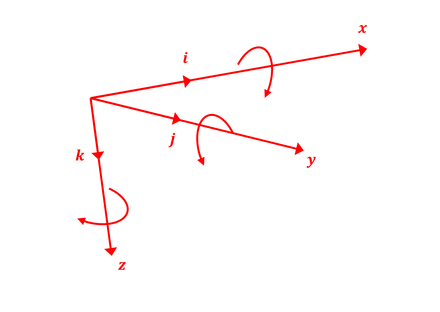
Fig-1: Coordinate system conventions#
Rotation Matrices#
Vectors that are expressed in different frames are related through a Direction Cosine Matrix (DCM), a \(3 \times 3\) rotation matrix [HS].
Notation
c4dynamics names a rotation matrix by two letters in square brackets. The letters state the direction of the transformation, read from right to left: \([BR]\) (Body from Reference) takes a vector that is expressed in \(R\) and returns the same vector expressed in \(B\):
The same notation applies to any pair of frames, for example:
\([BR]\) |
Body from Reference. Provided by
|
\([RB]\) |
Reference from Body. Provided by
|
\([BI]\) |
Body from Inertial, i.e. \([BR]\) when the reference frame is inertial. Used in the IMU, the magnetometer, and the quadcopter model |
\([SB]\) |
Sensor from Body, e.g. the gimbal of a seeker |
Properties
Direction cosines. The element \([BR]_{ij}\) is the cosine of the angle between the \(i\)-th axis of \(B\) and the \(j\)-th axis of \(R\). Hence the rows of \([BR]\) are the body axes expressed in \(R\), and its columns are the reference axes expressed in \(B\).
Inverse. A rotation matrix is orthonormal, \([BR] \cdot [BR]^T = I_3\), and its determinant is \(+1\). Its inverse is its transpose, which is the transformation in the opposite direction:
Composition. A chain of transformations is composed by cancelling adjacent letters. For three frames \(A, B, C\):
For example, a seeker that is mounted on a gimbal sees the reference frame through \([SR] = [SB] \cdot [BR]\).
Passive rotation. The rotation matrices in c4dynamics are passive: they rotate the frame of coordinates rather than the vector. The vector itself is unchanged; only the frame in which its components are expressed changes. To rotate a vector actively by a positive angle within the same frame, use the transpose. E.g. \(R_z(\psi)^T \cdot v\) rotates \(v\) by \(\psi\) about \(z\).
Elementary rotations
A rotation of a frame through an angle about one of its axes is given by an elementary rotation matrix:
These are implemented by rotx,
roty, and
rotz.
Any attitude is reached by a sequence of three elementary rotations.
Attitude Representations#
The attitude of a body is the orientation of its body frame \(B\) relative to the reference frame \(R\). It has three degrees of freedom, and c4dynamics represents it in three equivalent ways: three Euler angles, a rotation matrix \([BR]\), and a unit quaternion. The rotation matrix is the one that moves vectors between the frames. The Euler angles and the quaternion are the compact forms that are stored in the state vector and propagated in time (see Kinematics).
Euler Angles#
When Euler angles are employed in the transformation of a vector expressed in one reference frame to the expression of the vector in a different reference frame, any order of the three Euler rotations is possible, but the resulting transformation equations depend on the order selected [MIs].
In aerospace applications, the common order is that the first Euler rotation is about the z-axis, the second is about the y-axis, and the third is about the x-axis. Such a transformation order is called z-y-x, or 3-2-1. With reference to a body orientation, the resulting order is yaw, pitch, and roll. With reference to geographical orientation, the resulting order is azimuth (heading), elevation (pitch), and roll (bank angle).
c4dynamics adopts the 3-2-1 order. Starting with the body frame aligned with the reference frame:
Rotate about \(z_b\) through the yaw (heading) angle \(\psi\),
Rotate about \(y_b\) through the pitch angle \(\theta\),
Rotate about \(x_b\) through the roll angle \(\varphi\).
The rotations are applied in the order yaw, pitch, roll.
The angles, however, are listed in the opposite order, roll, pitch, yaw,
\((\varphi, \theta, \psi)\), wherever they appear as a group:
in the state vector of a rigidbody,
in the arguments of dcm321
and euler2quat,
and in the outputs of dcm321euler
and quat2euler.
This documentation follows the same order.
The first rotation is the rightmost in the product:
where \(c \equiv \cos\) and \(s \equiv \sin\).
This matrix is computed by dcm321.
The Euler angles are extracted back from the matrix by:
Gimbal lock. At \(\theta = \pm 90°\), \([BR]_{11}, [BR]_{12}, [BR]_{23}, [BR]_{33}\) all vanish, the roll axis is aligned with the yaw axis, and \(\varphi\) and \(\psi\) describe the same rotation. Only their sum (or difference) is defined, not each one alone. Any set of three angles has such a singular attitude. The consequence for the propagation of the angles in time is discussed in Kinematics.
Quaternion#
According to Euler’s rotation theorem, any attitude is reached from the reference frame by a single rotation through an angle \(\alpha\) about a unit axis \(n = [n_x, n_y, n_z]\). The attitude quaternion encodes this rotation by four parameters, scalar first (the Hamilton convention):
Where:
\(q_w\) is the scalar part of the quaternion
\(q_x, q_y, q_z\) are the vector part of the quaternion
Four parameters describe three degrees of freedom, therefore the quaternion is subject to one constraint. An attitude quaternion is a unit quaternion:
\(q\) and \(-q\) represent the same attitude (a rotation of \(\alpha\) about \(n\) equals a rotation of \(\alpha - 360°\) about the same axis). Unlike the three Euler angles, the quaternion has no singular attitude [DI].
Rotation matrix
The quaternion describes the rotation that carries the reference frame onto the body frame. The matrix that c4dynamics computes from a quaternion is the Body from Reference DCM, \([BR]\): it takes a vector expressed in the reference frame and returns the same vector expressed in the body frame, \(v_B = [BR] \cdot v_R\):
Some references give instead the matrix that rotates a vector by \(\alpha\) about \(n\). That matrix is the transpose, \([RB]\), and its off-diagonal terms that contain \(q_w\) have opposite signs. The difference is in the direction of the transformation, not a sign error. In quaternion products, \(v_B = [BR] \cdot v_R\) is \([0, v_B] = q^* \otimes [0, v_R] \otimes q\), where \(q^* = [q_w, -q_x, -q_y, -q_z]\) is the conjugate of \(q\).
For example, the quaternion of a yaw of \(90°\),
\(q = [\cos 45°, 0, 0, \sin 45°]\),
gives \([BR] = R_z(90°)\), the elementary rotation above.
In general, a quaternion describes the same attitude as the 3-2-1 Euler angles
of the convention above, and its \([BR]\) is identical to
dcm321 of those angles.
It is computed by quat2dcm.
Relation to the Euler angles
The quaternion of the attitude that is defined by the 3-2-1 Euler angles \((\varphi, \theta, \psi)\) is given by:
The inverse relation, from a quaternion to the Euler angles, is given by:
The extracted Euler angles are, of course, still singular at \(\theta = \pm 90°\).
The quaternion itself is not.
The quatbody state object therefore
stores the quaternion, and computes the Euler angles only for presentation.
Conversions#
The functions of the rotmat module convert between the three representations:
From \ To |
Euler angles \((\varphi, \theta, \psi)\) |
DCM \([BR]\) |
Quaternion \(q\) |
|---|---|---|---|
Euler angles |
- |
||
DCM |
|
- |
|
Quaternion |
- |
Notes:
All the functions take and return angles in radians, except
dcm321euler, which returns degrees.All the matrices are \([BR]\). To get \([RB]\), transpose the result.
A conversion that passes through the Euler angles inherits their singularity at \(\theta = \pm 90°\).
Between ENU and NED
The ENU and the NED frames swap \(x\) and \(y\) and flip \(z\). The matrix that does it is its own inverse, so the same matrix converts both ways:
A heading measured from east (ENU) becomes a heading measured from north (NED): \(\psi_{NED} = \pi / 2 - \psi_{ENU}\). This conversion is used at the MAVLink boundary of the ArduPilot simulation.
Examples#
Import c4dynamics and numpy:
>>> import c4dynamics as c4d
>>> import numpy as np
Elementary rotations
A frame that is rotated by \(90°\) about \(z\). The \(x\) axis of the original frame is the \(-y\) axis of the rotated frame:
>>> c4d.rotmat.rotz(90 * c4d.d2r) @ [1, 0, 0]
[0  -1  0]
The transpose rotates the vector itself (active rotation) by \(90°\) about \(z\), from \(x\) to \(y\):
>>> c4d.rotmat.rotz(90 * c4d.d2r).T @ [1, 0, 0]
[0  1  0]
The 3-2-1 matrix is the product of the three elementary rotations:
>>> phi, theta, psi = 10 * c4d.d2r, 20 * c4d.d2r, 30 * c4d.d2r
>>> BR = c4d.rotmat.dcm321(phi, theta, psi)
>>> np.allclose(BR, c4d.rotmat.rotx(phi) @ c4d.rotmat.roty(theta) @ c4d.rotmat.rotz(psi))
True
It is orthonormal, so its transpose is its inverse:
>>> np.allclose(BR @ BR.T, np.eye(3))
True
>>> np.linalg.det(BR)
1
From reference to body and back
The inertial velocity of an aircraft flying north, expressed in an earth frame, and its attitude, a pitch of \(30°\):
>>> v_R = [150, 0, 0]
>>> BR = c4d.rotmat.dcm321(theta = 30 * c4d.d2r)
The velocity expressed in the body frame, \(v_B = [BR] \cdot v_R\):
>>> v_B = BR @ v_R
>>> v_B
[129.9  0  75]
And back to the earth frame, \(v_R = [RB] \cdot v_B = [BR]^T \cdot v_B\):
>>> BR.T @ v_B
[150  0  0]
The body axes in the reference frame
A body with heading \(\psi = 90°\) and pitch \(\theta = 30°\). \([BR]\) expresses the reference \(x\) axis in body coordinates, and \([RB] = [BR]^T\) expresses the body \(x\) axis (the nose) in reference coordinates. The latter is also the first row of \([BR]\):
>>> BR = c4d.rotmat.dcm321(theta = 30 * c4d.d2r, psi = 90 * c4d.d2r)
>>> BR @ [1, 0, 0]
[0  -1  0]
>>> BR.T @ [1, 0, 0]
[0  0.866  -0.5]
>>> BR[0]
[0  0.866  -0.5]
The state objects provide these matrices for their current attitude:
>>> rb = c4d.rigidbody(theta = 30 * c4d.d2r, psi = 90 * c4d.d2r)
>>> rb.RB @ [1, 0, 0]
[0  0.866  -0.5]
Composing transformations
A target position relative to a seeker, expressed in the reference frame, and a seeker body with a heading of \(30°\):
>>> dx = [1000, 1000, 0]
>>> skr = c4d.rigidbody(psi = 30 * c4d.d2r)
The relative position in the body frame and the azimuth angle to the target:
>>> x_b = skr.BR @ dx
>>> x_b
[1366  366  0]
>>> np.arctan2(x_b[1], x_b[0]) * c4d.r2d
15
A gimbal that turns the sensor by another \(15°\) about \(z\) gives \([SB]\). The sensor sees the reference frame through \([SR] = [SB] \cdot [BR]\), which puts the target on its boresight:
>>> SB = c4d.rotmat.rotz(15 * c4d.d2r)
>>> SR = SB @ skr.BR
>>> SR @ dx
[1414.2  0  0]
The two \(z\) rotations add up:
>>> np.allclose(SR, c4d.rotmat.rotz(45 * c4d.d2r))
True
Converting between representations
From the Euler angles to the DCM and back. Note that
dcm321euler returns degrees:
>>> BR = c4d.rotmat.dcm321(10 * c4d.d2r, 20 * c4d.d2r, 30 * c4d.d2r)
>>> c4d.rotmat.dcm321euler(BR)
(10  20  30)
From the Euler angles to a quaternion, and from the quaternion to the DCM and to the Euler angles (in radians):
>>> q = c4d.rotmat.euler2quat(10 * c4d.d2r, 20 * c4d.d2r, 30 * c4d.d2r)
>>> q
[0.952  0.038  0.189  0.239]
>>> np.allclose(c4d.rotmat.quat2dcm(q), BR)
True
>>> c4d.rotmat.quat2euler(q) * c4d.r2d
[10  20  30]
From the DCM to a quaternion, through the Euler angles:
>>> np.allclose(c4d.rotmat.euler2quat(*np.array(c4d.rotmat.dcm321euler(BR)) * c4d.d2r), q)
True
The matrix of a quaternion is the Body from Reference DCM. A yaw of \(90°\) gives the elementary rotation \(R_z(90°)\):
>>> q90 = [np.cos(45 * c4d.d2r), 0, 0, np.sin(45 * c4d.d2r)]
>>> np.allclose(c4d.rotmat.quat2dcm(q90), c4d.rotmat.rotz(90 * c4d.d2r))
True
\(q\) and \(-q\) are the same attitude:
>>> np.allclose(c4d.rotmat.quat2dcm(-q), c4d.rotmat.quat2dcm(q))
True
quat2euler also converts an array of quaternions,
e.g. the attitude history of a quatbody:
>>> c4d.rotmat.quat2euler(np.array([q, -q])) * c4d.r2d
[[10  20  30]
 [10  20  30]]
Between ENU and NED
>>> enu2ned = np.array([[0, 1, 0], [1, 0, 0], [0, 0, -1]])
>>> enu2ned @ [3, 4, 5]
[4  3  -5]
>>> np.allclose(enu2ned @ enu2ned, np.eye(3))
True
References#
Hanspeter Schaub, “Spacecraft Dynamics and Control” lecture notes, module 2: rigidbody kinematics.
Ch 4 in “Missile Flight Simulation Part One Surface-to-Air Missiles”, Military Handbook, 1995, MIL-HDBK-1211(MI).
Diebel, J., 2006, “Representing Attitude: Euler Angles, Unit Quaternions, and Rotation Vectors”, Stanford University.
See Also#
Next: the propagation of the position and the attitude in time |
|
Direction Cosine Matrices for a rotation about the \(x\), \(y\), \(z\) axes |
|
Direction Cosine Matrix for a sequence of rotations in following order: \(z\), then \(y\), then \(x\) |
|
Extract Euler angles (roll, pitch, yaw) from a Direction Cosine Matrix (DCM) of 3-2-1 order |
|
Attitude quaternion of 3-2-1 Euler angles |
|
3-2-1 Euler angles of an attitude quaternion (radians) |
|
Body from Reference Direction Cosine Matrix of an attitude quaternion |
|
Rigid body object with an Euler angles attitude |
|
Rigid body object with a quaternion attitude |
|
Animates the rigid body’s motion using a 3D model according to the 3-2-1 Euler angles histories. |